Other projects from this group
IR Remote Control (infrared) Programmable and With Code Learn
IR Remote Control project with 13 channel, infrared diode, photodiode (for code learning) and ATTiny13A AVR microcontroller
Source Code, BOM, PCB and Schematic Files of Programmable IR Remote With Code Learn With ATTiny13A - Rev 1.4
Price:
Other projects from this group
This project is a “Programmable and Code Learn IR Remote (InfraRed) With ATTiny13A”. ATTiny13A is a low-cost AVR microcontroller with 8 pins (6 I/O) and 1KB memory.
There are two folders in this project, “PCB-SCH-BOM” and CodeVision Source.
In the source code folder there is a pre-compiled file in the “HEX” folder. To re-compile or check out the source code, open “IRRemote.prj” with codeVision AVR software.
Here’s the fuse setting:
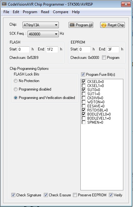
The microcontroller uses its internal 9.6MHz oscillator. Also the BOD is enabled to check the voltage if it is not under 2v. A 3V CR2032 battery can be used for 6 months.
- The fuse high byte is 0xFC and the low byte is 0xFA.
- PORTB5 is an IO pin in this project, which means you can program the chip only one time with SPI programmers. If you are going to re-program it, use AVR parallel programmers or AVR unlockers (e.g. Dr Fuse).
- Also the ATtiny13A can be programmed by WiCardKit 1 in the HV (parallel) method.
In the “PCB-SCH-BOM” folder, there are 6 files:
- IRRemote.prjpcb (Altium project)
- IRRemote_PCB.pcbdoc (Altium PCB file)
- IRRemote_SCH.schdoc (Altium schematic file)
- IRRemote_BOM.txt (Bill of materials)
- IRRemote_SCHPDF.pdf
- IRRemote_PCB_DIPTRACE (DipTrace PCB file)
The PCB file has been made by “Altium”, also there is a “PDF” and “DipTrace” file of the schematic and PCB in the project files.
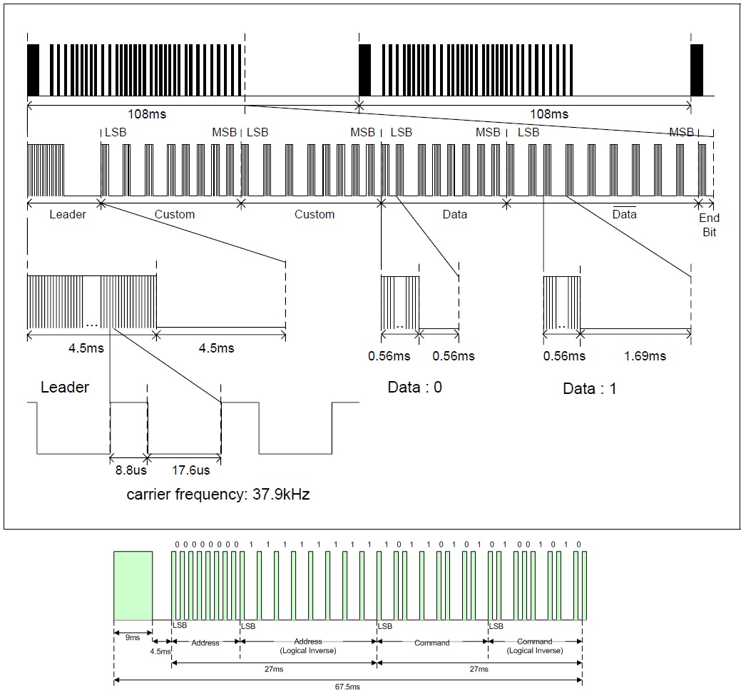
The IR Remote Protocols
IR Remote has 13 push buttons which each of these buttons can be programmed manually or can copy a code from another supported IR Remote into the channel’s memory.
This Infrared remote supports two of the most common IR 32 bit data transaction protocols:
- A 9mS leader signal with 37 KHz carrier. The second byte of data is a copy of the first data and the fourth byte is inverted code of the third data. This protocol is used in SAMSUNG TV remotes.
- A 13.5mS leader signal with 37 KHz carrier. The second byte of data is an inverted code of the first data and the fourth byte is inverted code of the third data. This protocol is used in NEC remotes.
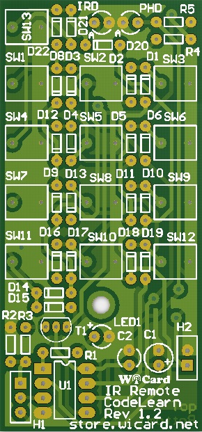
The IR Remote Board
The PCB dimension is 35*75mm and has been designed in two layers (metalized PCB). There is a 3mm pad in the middle bottom of the PCB and you can re-locate it according to your enclosure.
H2 is for the power source input (3-5V) and H1 is a 3 pin header. It’s necessary to use a jumper for the H1 pin header. With placing a jumper on pad1 (square pad) and pad2 of H1, the device will turn on in normal “Infrared remote” mode. After placing the Battery, The LED1 will blink for 0.5 second and turns off. With placing the jumper on pad3 and pad2, the device will turn on in “Code Learn” mode. After plugging the power, LED1 turns on and remains on.
By holding “SW12” during the power on (for at least 1 second), the device will turn on in manual programming mode (in case the jumper is on pad1 and pad2) and LED1 will remain on.
Manual Programming
First of all place the jumper on pad1 and pad2 and turn on the remote in “manual programming mode” by holding “SW12” during the power on (for at least 1 second). LED1 will remain on.
Now choose a channel between 13 push buttons and push the button, LED1 will turn off. Then insert a number between 00000 and 65535 (five digits). SW1 is 1, SW2 is 2, … SW9 is 9 and SW10 is 0.
Every time you push a button, LED1 would be toggled. When you insert the fifth digit, the LED1 will blink multiple times which means the code has been saved.
Code Learn Method
Turn on the remote in code learn mode (put the jumper on pad2 and pad3 before power on). Choose a channel and LED1 will turn off. Hold a supported IR remote control in front of the photo diode. Push a button. If LED1 blinks multiple times, that means the channel received the button’s code and has been programmed.
1.4
- Transmit debug
- Coding debug
- Supported remotes increased
1.3
- Code Learn Channel bug fixed
- The sending time increased
1.2
- Code Learn feature
- Adding one more channel
- DipTrace PCB
1.1
- Manual Channel Programming
- Status LED
1.0
- Infrared Remote PCB design
- Source code and programming
- 12 channels