Other projects from this group
WiCardKit 1.0 Board (Hardware) Project-Programmer and USBtoSerial
WiCardKit 1.0 board project. This board and the software contains AVR high voltage programmer (parallel programmer) and a USBtoSerial interface.
Source code, Schematics and PCB plans of WiCardKit 1 programmer board - Rev 1.1
Price:
Other projects from this group
The high voltage (parallel) programming method is the highest layer of access to the microcontroller memories and programming. This method can unlock the AVR/PIC chips which can’t be programmed by regular programmers while the chips work well.
The other feature is the “reset” pin in some the microcontrollers can be accessible as an IO with high voltage programming.
High voltage means a voltage a bit more than the typical voltage of the microcontroller which is 12V for the AVR microcontrollers and 13V for the PIC microcontrollers.
This voltage can only be applied on the “reset” pin under the specific condition.
The WiCardKit 1.0 contains tools for the programmable based circuit designs, such as the circuit with microcontrollers or arduino and etc.
In the current revision, in addition to the AVR parallel programmer, there is a USBtoSerial interface which lets the user to upload the programs on espressif modules.
The following AVR microcontrollers can be programmed with the high voltage method with WiCardKit 1.0:
ATtiny13A
ATmega48P
ATmega48V
ATmega8
ATmega8A
ATmega8L
ATmega88P
ATmega88V
ATmega16A
ATmega168P
ATmega168PV
ATmega32A
ATmega328P
This board has a ZIF socket which an AVR Dip microcontroller can simply be placed on it. Also has a 6pin header for the PIC microcontrollers ICSP and UART Rx-Tx.
Con1 is for the USB B cable and Con2 is for the 5mm 12-15V power source jack.
- Always first plug the power jack, then the USB cable.
- Always first unplug the USB cable, then the power jack.
- The voltage under 12V of the power source, may cause error in programming.
To programming the microcontrollers, always place a jumper on pin 1 (square) and pin 2 of the H1 pin header.
The H2 pins:
- PIC microcontrollers reset (square pin)
- 5V or 3.3V power (selectable by H3)
- Ground
- PIC microcontrollers PGD – UART RxD
- PIC microcontrollers PGC – UART TxD
- PIC microcontrollers PGM
H3 is the ICSP voltage selector. Jumper on pin 1 (square) and pin 2 is 3.3V and on pin 2 and 3 is 5V.
- H3 can supply the circuit separate-ly
- More than 100mA current drain from 5V is not allowed.
- More than 700mA current drain from 3.3V (or 90mA in case of not using an external power source) is not allowed.
Dip Switch Configuration
Setting the dip switches correctly is the most important. To avoid hurting the programmer or the microcontroller, configure the switches carefully.
The Dip switch has 8 separate 0/1 switches which must be set before placing the microcontroller on the ZIF socket.
- First turn off all of the switches
The configuration will be shown in the manual picture of the WiCardKit Software which is the same as the following modes:
- ATtiny13A microcontrollers:
All off, only switch number 2 on
- ATmega8P-ATmega48V-ATmega8-ATmega8A-ATmega8L-ATmega88P-ATmega88V- ATmega168P-ATmega168PV-ATmega328P microcontrollers:
All off, only 2,4,6 on
- ATmega16A-ATmega32A:
All off, only 1,4,5,7 on
PIC18F4550 Programming
This microcontroller can be programmed by MPLAB IDE or PICKit2 and the PICKit2 programmer.
The configuration bytes value:
CONFIG1L(300000) = 0x20
CONFIG1H(300001) = 0x0E
CONFIG2L(300002) = 0x39
CONFIG2H(300003) = 0x1E
CONFIG3L(300004) = ----
CONFIG3H(300005) = 0x01
CONFIG4L(300006) = 0x81
CONFIG4H(300007) = ----
CONFIG5L(300008) = 0x0F
CONFIG5H(300009) = 0xC0
CONFIG6L(30000A) = 0x0F
CONFIG6H(30000B) = 0xE0
CONFIG7L(30000C) = 0x0F
CONFIG7H(30000D) = 0x40
WiCardKit Driver Installation
In the “WiCard Kit 1.0 WinDriver” folder there is a driver installation file. After plugging the USB cable of the WiCardKit board, install the driver.
- Also you can install the driver manually from “Driver” folder and device manager
- After the driver installation, unplug the board’s USB cable then plug it again after 30 seconds
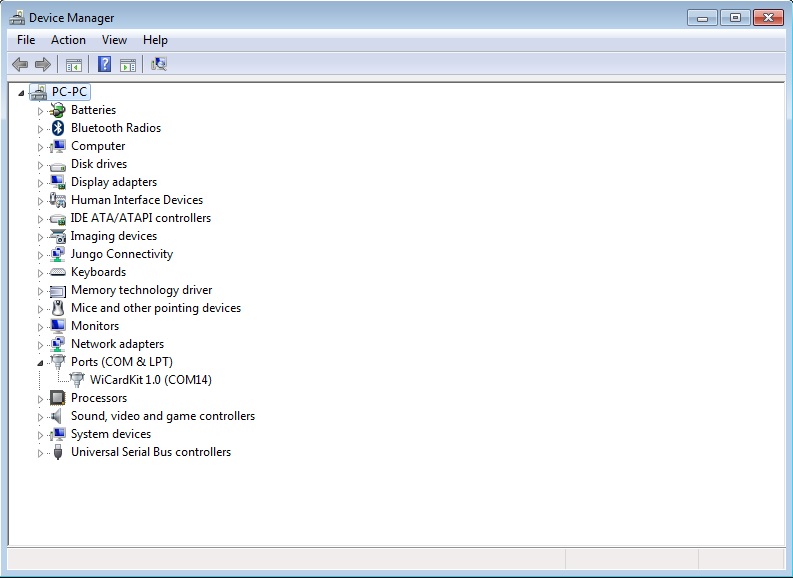
In case the driver has been installed probably, you can see the device’s COM port in the device manager window.
Software Installation
To installation go to “Software Bin” folder and click on “setup”, then in the installation window, click on “Install”.
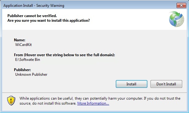
The software will be installed automatically and a shortcut icon will be added on your desktop. It will run automatically right after setup and will ask you to select “COM” port.
Hardware Detection
After plugging the WiCardKit 1.0 board USB cable, select the COM port of the board.
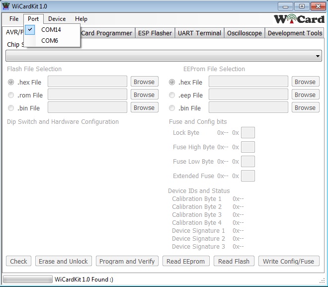
In case everything is ok, “WiCardKit 1.0 Found” will be appeared in the bottom of the window.
Chip Programming
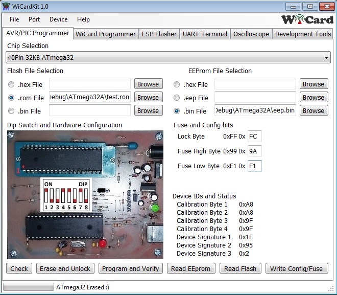
For the chip programming, first select your chip from “chip selection” drop down menu.
The “Dip Switch” configuration of the board will appear and configure the switches.
You can choose and select one of the .hex, .rom and .bin forma files for the flash and .hex, .eep, .bin for the eeprom memory programming.
In the “Fuse and Config Bits” section you can see and set the lock and fuse bits value.
The “Device IDs and Status” section show microcontroller IDs and calibration bytes.
“Check” button reads the Device IDs, calibration, lock and fuse bytes.
“Erase and Unlock” erases the flash memory (and eeprom if eesave is not programmed) and then set the fuse bits to default, so the chip can be programmed with regular serial programmer.
“Program and Verify” erases the flash memory and then programs the selected files into the chip and finally will program the fuse bits if have been set.
“Read EEprom” reads the eeprom memory and saves it as a .bin file.
“Read Flash” reads the flash memory and saves it as a .bin file
“Write Config/Fuse” programs the fuse and lock bit data.
1.0
- Schematics design
- PCB design
- Programming
- Future features prediction