Other projects from this group
ESP32 WiFi ECG (Oximerer/Heart-Rate/Blood pressure/Temperature)
With this Arduino source code, a MAX30100 Pulse Oximeter module and an ESP32 WiFi module make a WiFi ECG Monitor with Network feature and nice responsive WebApp
ESP32-MAX30100 WiFi ECG Monitor (HeartRate/Blood Pressure/Oximeter/Temperature Diagram) Arduino Source Code- Rev 1.1
Price:
Other projects from this group
This project is an ESP32 WiFi “ECG Monitor” and “Pulse Oximeter” firmware with Chain Network feature. The “Chain Network” is a local network which the devices one by one are connected to the each other.
This project is based on the “ESP32 WebApp Builder” project which is a base source code with the chain network feature.
There are the following files in this project:
- ESP32ECGMonitor.ino (Main handler file)
- AC.h (Configuration header file)
- AC.ino (Configuration handler file)
- functions.ino (System functions)
- rootPage (UI handler file)
- user_global.h – Project global variables and definitions file.
- user_init.ino – Project initial script file.
- user_loop.ino – This file has a “userLoop()” function which calls repeatedly (like arduino “loop()” function).
- user_settings.ino – Project settings file.
- user_main.ino – ECG monitor handler script.
- user_sub.ino – Network pulse oximeter handler script.
- user_global.ino – This file has a “userGlobal()” function which calls at the same time in all of the devices in the network. This function will be called when the app sends a command to the network (after userMain and userSub).
- Webapp.h – This file contains the WiFi ECG WebApp’s script.
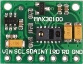
MAX30100, Pulse Oximeter Module
The MAX30100 is an integrated pulse oximetry and heart-rate monitor sensor solution. It combines two LEDs, a photo-detector, optimized optics, and low-noise analog signal processing to detect pulse oximetry and heart-rate signals.
The MAX30100 communicates with ESP32 via two wire (I2C) interface.
ESP32 and MAX30100 WiFi ECG Schematic
In this project, GPIO4 works as the I2C SDA and the GPIO 5 works as the I2C SCL. Use the following schematic for the connections:
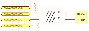
The schematic is simple, either you can place both of the ESP and MAX30100 module (e.g. including two 1.5V battery) in an enclosure or in two different enclosures and connect the MAX30100 to the ESP via a 4-wires cable.
- If you are using a standard MAX30100 module, there’s no need to use pull up resistors.
- It’s suggested use two 33 ohm load resistors in the transaction wires.
The Chain Network
The “Chain Network” is a local network which the devices one by one are connected to the each other (Series). In the chain network, the first device is the master of network. The starter (either the master or the last joined module) is directly connected to the WebApp. It sends the command to the next device, and the next device sends it to the next one till the last device. The last device response will be sent to the first device and finally the WebApp via the middle devices.
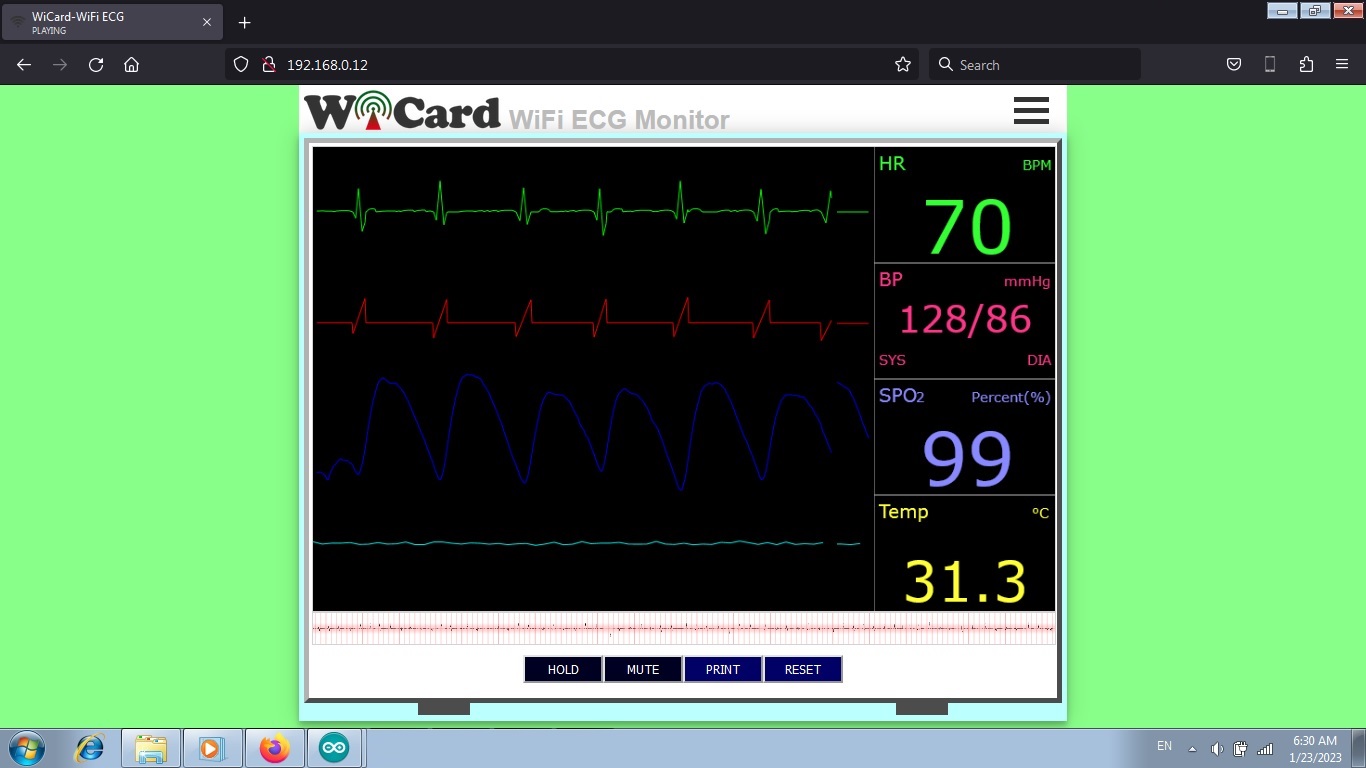
The WiFi ECG Monitor Web Application
First of all place your top of your finger on the MAX30100 sensor’s eye and then open the root page.
The WiFi ECG project has a nice and responsive web application which is placed in the root page address (192.168.4.1 by default and can be set to 192.168.5.1 or you can use the router’s DHCP IP).
The graphs update in every 6 seconds. That means the graphs show the values which has been captured 6 seconds ago.
The green value (HR) is the average heart-rate value of the last 6 seconds in “Beats Per Minute” (BPM) unit.
The purple value (BP) is the blood pressure “Systolic” (SYS) and Diastolic (DIA) values in the mmHg unit.
The blue value (SPO2) is the percent of saturated oxygen in the blood.
The yellow value (Temp) is the temperature of sensor (which should be equal with the finger’s top temperature) in the Celsius unit.
- Try to wrap something around your finger and the MAX30100 module, because this module is very sensitive on the peripheral lights.
- When the temperature of the top of the finger is between 32 and 35, the values are more accurate.
- When you see red “E” sign, “NaN” values or incorrect values (too high/too low), that means the finger is not placed on the sensor correctly, the finger is not warm enough or the sensor/finger is shaking.
- The blood pressure value depends on many things. Top of the finger is not a good point for measuring the blood pressure though, but if you set the regulation values correctly, you may receive more accurate value for the blood pressure.
- When a value repeats for many times, that means the correct average value.
- This is not medical equipment, even if the result value be accurate, because this project has not been tested on a huge number of patients. Please do not use for the patients.
There are 2 toggle buttons under the monitor screen:
- HOLD: Holds the capturing.
- MUTE: Toggles between playing and muting the hurt-rate beep sound.
And 2 push buttons:
- PRINT: Prints the first one minute heart-rate graph in a .png file.
- RESET: Clears the screen and heart-rate diagram.
The responsive WebApp
This web application is also compatible with cell phone and mobile device browsers
The menus
The Web Application is divided to 3 menus. The menus can be selected by click on the menu button
“ECG” refers to the WiFi ECG monitor page, “HR-SPO2” refers to the Network Pulse Oximeter and heart-rate page and “Settings” refers to the settings page.
The Network Pulse Oximeter and Heart-rate
In the “HR-SPO2” page, there are 16 channel rows of the volt meters result. That means you can add up to 16 devices to the chain network and see the values at the same time.
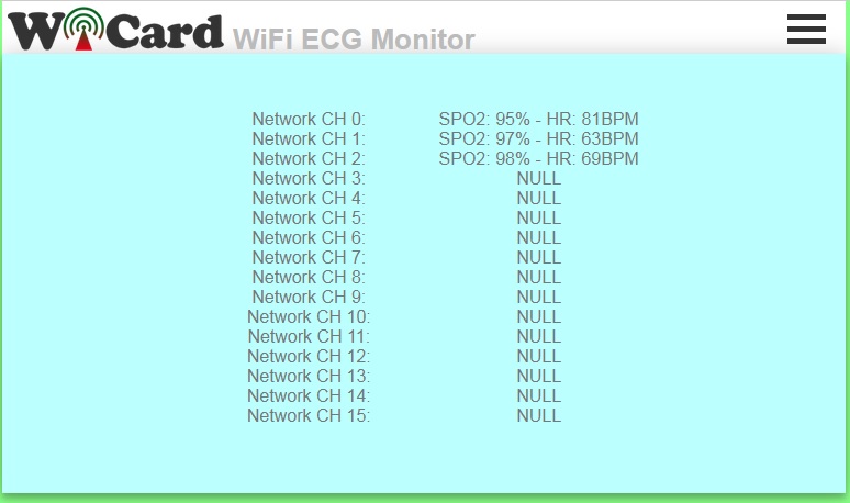
In the above picture, only three devices (CH0, CH1 and CH2) are connected to the network.
The “HR-SPO2 Network Channel” can be set in the settings menu.
- The actual heart-rate and SPO2 value is the average of received values.
- If you receive 0 or a value with two much difference, that means the finger has not well placed on the sensor or the finger (or sensor) is not warm enough.
The Settings menu
The web application’s settings menu has been divided to 5 parts:
- Modem Configuration
In this section you can see the available access points, the connection status, the device MAC address and the DHCP IP.
Also in this section you can set the SSID and password of the modem’s access point. - Device Hotspot Configuration
In this section you can set your module’s hotspot SSID and password.
The secure link is a string which will be added at the end of your module’s IP address. For example if you set it “123”, the IP address of the WebApp of your module will be 192.168.4.1/123 instead 192.168.4.1
The even means the default IP is 192.168.4.1, the Odd means the default IP is 192.168.5.1
Hidden HotSpot will set the HotSpot hidden.
Temporary HotSpot will disable the HotSpot right after the module is connected to the modem or joined to the network (For the last device in the network). - System Configuration
In this section:
You can set the device’s HR-SPO2 network channel. The channel must be a number between 0-15 and the devices can’t have the same channel.
SPO2 offset, SYS offset and DIA offset is the off-set value according to the difference of the correct result (which has been measured with a standard device) to the project result. The middle value is 128 and you can decrease or increase it. - Local Network Configuration
In this section you can set the “Master” device and also set the userGlobal() function execution delay.
The linked WiCard IP is the IP of linked device to the module’s access point.
If you don’t turn on the “Join Required” switch, the module will be set as Master. - Local Network Map
In this section, the attached devices in the chain network will be shown.
For the master, it starts with master’s SSID, then the second ESP device, until the last one, but for the last device, the sort is vice versa.
With typing the target device SSID in the target text-box, the oscilloscope will show the target device signal.
- Both of ESP32 and ESP8266 can transfer the oscilloscope data of the other modules in the network.
- You can directly access to the settings menu with http://ip#settings link (e.g. 192.168.4.1#settings).
Programming Manual
For the programming, use the pre-defined functions in the files which start with “user”.
Add your start-up script to the “userInit()” function in user_init.ino file. No need to do wifi or server configuration. This configuration already have done in the firmware system files (e.g. systemInit() and setup()).
The “userLoop()” function (user_loop.ino) calls repeatedly (like arduino “loop()” function), If your program needs to execute a statement repeatedly (e.g. reading a sensor’s data), insert your script in this function.
The “webapp.h” file is the root page’s script. You can customize sWebApp variable in that file if you’re going to make changes in the Web UI.
Also you can customize the “userGetSettings()” function (user_settings.ino), for adding more settings to the firmware. The WebApp execute this function when you click on the Settings menu.
After you click on the SAVE button of the user-defined settings, the “userSetSettings()” functions will be called.
The settings will not be shared in the network and each device has its own settings.
The “userMainInit()” in the “user_main.ino” file, calls once and only just in the network starter when you click on the “ECG” menu (or initially after loading the root page). You can initiate the uiAppData (which is the offset values in this project) in this function.
The “userMain()” in the “user_main.ino” file, calls intervally.
The “userSubInit()” in the “user_sub.ino” file, calls once and only just in the network starter when you click on the “HR-SPO2” menu.
The “userSub()” in the “user_sub.ino” file, calls intervally. The WebApp will send the uiAppData to this function and then it can be transferred in the chain network.
- Only if you call “globalCmdEnable();” function at the end of “userMainInit()”, “userMain()”, “userSubInit()” and “userSub()”, the uiAppData will transferred in the chain network.
- The “networkStarterCheck()” bool functions says whether the module is the network starter or not.
The “userGlobal()” function in the “user_global.ino” file calls at the same time in all of the devices in the chain network after the “CMD delay” time.
- If you are going to use this function, set the menu’s interval time to 0.
- This function always will be called after setting the “globalCmdEnable()”.
- It’s recommended to use a bool variable when you are going to use this function after a change in an element occurs.
In the AC.h file, if you remove “#define LOG_ENABLE”, the logs will not be shown and the log memory would be released.
In the user_global.h file, you can set the default I2C pins and speed by the following “define” variable:
#define SDA_PIN%26nbsp;%26nbsp;%26nbsp;%26nbsp;%26nbsp;%26nbsp;%26nbsp;%26nbsp;%26nbsp;%26nbsp;%26nbsp;%26nbsp;%26nbsp;%26nbsp;%26nbsp;%26nbsp;%26nbsp;%26nbsp;%26nbsp;%26nbsp; 4
#define SCL_PIN%26nbsp;%26nbsp;%26nbsp;%26nbsp;%26nbsp;%26nbsp;%26nbsp;%26nbsp;%26nbsp;%26nbsp;%26nbsp;%26nbsp;%26nbsp;%26nbsp;%26nbsp;%26nbsp;%26nbsp;%26nbsp;%26nbsp;%26nbsp; 5
#define I2C_SCL_FREQ%26nbsp;%26nbsp;%26nbsp;%26nbsp;%26nbsp;%26nbsp;%26nbsp;%26nbsp; 100000
#define I2C_SLAVE_ADDR%26nbsp;%26nbsp; 0x57
If you “un-log” this parameter: #define MAX30100_TEST_MODE, the device will turn on in test mode, which shows IR and Red LED values only in the serial monitor. These two values should be close to each other (less than 3000 unit difference).
By changing the LED power in the following line, the values will change:
#define LED_CONFIG_VAL%26nbsp;%26nbsp;%26nbsp;%26nbsp; RED_LED_11_MA|IR_LED_11_MA
- Usually the best value for both of RED and IR is 11 mA.
- If you have not enough programming and electronics knowledge, do not make changes.
- The WiFi signal strength takes effect on the module capability and the ECG streams.
It’s pretty important that how the finger is placed on the MAX30100 Sensor’s eye to receive correct and accurate values.
1.1
- The Web Ui upgraded
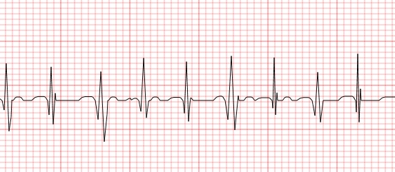
- The heart-rate diagram upgraded
- blood pressure diagram and calculations added
- 4 Buttons and features added
- Network pulse oximeter added
1.0
- Calculating SPO2
- Calculating Heartbeat-Rate
-Designing the ECG page
-Printing the diagrams