Other projects from this group
LAN (RJ-45) to WiFi Converter With ESP32 and ENC28J60 Module
With this source code, an ESP32 and an ENC28J60 LAN(RJ45) module, you can connect to your WiFi modem via LAN(RJ45) port of your computer
LAN to WiFi Converter with ESP32 and ENC28J60 Arduino Source Code - Rev 1.0
Price:
Other projects from this group
This project is a WiFi to LAN with “ENC28J60” and “ESP32” firmware arduino source code (.ino).
The project gives you an internet access via WiFi modem, over the LAN port (like USB WiFi stations).
Simply you can plug the ESP32 power, configure it with the modem’s SSID and Password, connect your PC or laptop to the “ENC” module with a RJ45 LAN cable and access to the internet.
The project contains the following files:
- ESP32ENCWiFiLan.ino (Main handler file)
- user_global.h – Project global variables and definitions file.
- user_init.ino – Project initial script file.
- user_loop.ino – This file has a “userLoop()” function which calls repeatedly (like arduino “loop()” function).
- user_settings.ino – Project settings file.
- user_global.ino – This file has the global functions.
- Webapp.h – This file contains the WebApp’s script.
Uploading the WiFi LAN project
First open one of the files with Arduino program, then set the settings as the following image (Board and Flash Frequency).
- The “Board” must be set on one of the ESP32 Modules before doing anything.
And then click on the upload button, the firmware will compile and automatically upload to the ESP32 module.
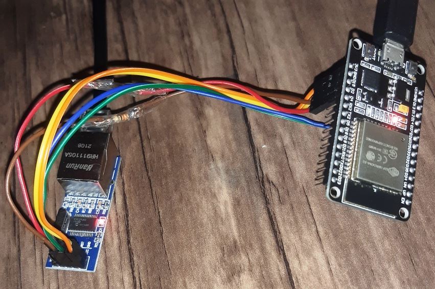
ENC28J60 LAN Module
This module (which is called “MINI ENC28J60” too) has an ENC28J60 chip, an RJ45 port and a pin header which lets you to communicate with the main chip via SPI protocol.
The chip converts LAN Rx and Tx data to the SPI protocol and buffer it until the host receives it and sends the response back.
The WiFi-LAN Schematics
The schematic is so simple. Just connect the wire as the following picture: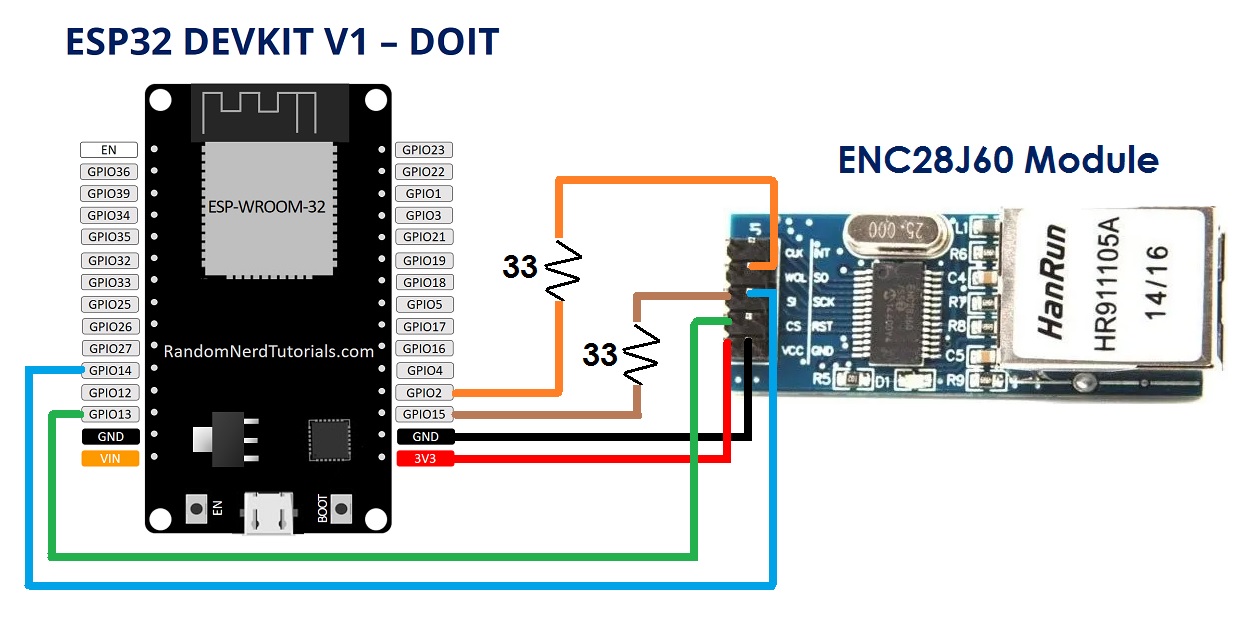
- If you are using another ESP32 board (or ESP32 Module), connect the wires to the same ESP32’s GPIO pins.
WiFi LAN Configuration
Before access to the internet via the LAN cable, setup the WiFi connections.
Then turn on the ESP32 module by plugging its USB cable and connect to its hotspot (WiCardWiFiLan by default). The default password is: 12345678
The default web application address is 192.168.4.1, insert the address in a web browser’s address bar to access to the configuration page.
- If you don’t have a WiFi support device, you can plug the LAN cable and go to 192.168.6.1 with a web browser.
The configuration has been divided to 5 parts:
- Modem Configuration
In this section you can see the available access points, the connection status, the device MAC address and the DHCP IP.
Also in this section you can set the SSID and password of the modem’s access point. - Device Hotspot Configuration
In this section you can set your module’s hotspot SSID and password.
The secure link is a string which will be added at the end of your module’s IP address. For example if you set it “123”, the IP address of the WebApp of your module will be 192.168.4.1/123 instead 192.168.4.1
The even means the default IP is 192.168.4.1, the Odd means the default IP is 192.168.5.1
Hidden HotSpot will set the HotSpot hidden.
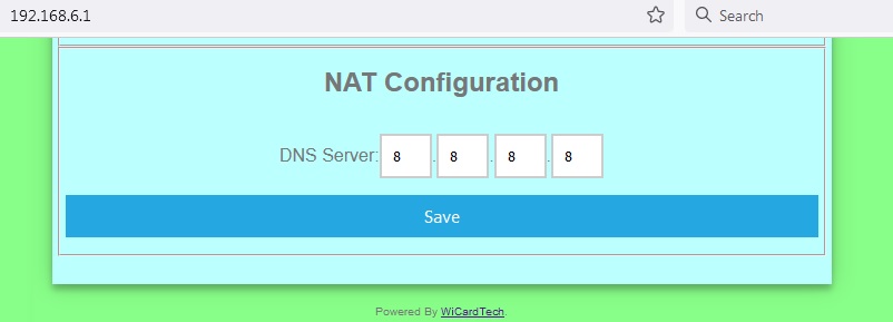
Temporary HotSpot will disable the HotSpot right after the module is connected to the modem or joined to the network (For the last device in the network). - NAT Configuration
In this section you can set the DNS server ip address. The default is: 8.8.8.8
Access to the Internet
After the configuration, re-start the module, wait for a few seconds until ESP32 registers itself to the WiFi modem.
Then plug the LAN cable in your PC or laptop.
- In case you are using windows 7, turn off your laptop WiFi device before plugging the LAN cable.
Wait for a few seconds until DHCP done. Then your PC or laptop IP would be 192.168.6.2 and the WiFi LAN IP would be 192.168.6.1 and you can access to the WiFi modem Internet via you WiFi LAN device.
- Due too low buffer size of ENC28J60 and the low process speed of ESP32, this firmware can handle a few connections at the same time. So it’s suggested do not open multiple tabs in your browser.
- This is the first release of this project, and it is a good tutorial for Ethernet, IP, TCP-UDP and DHCP headers. In the next releases I will try to increase the firmware abilities.
- This release doesn’t support “ping” command.
Programming Manual
For the programming, use the pre-defined functions in the files which start with “user”.
Add your start-up script to the “userInit()” function in user_init.ino file. No need to do wifi or server configuration. This configuration already have done in the firmware system files (e.g. systemInit() and setup()).
The “userLoop()” function (user_loop.ino) calls repeatedly (like arduino “loop()” function), If your program needs to execute a statement repeatedly (e.g. reading a sensor’s data), insert your script in this function.
The “webapp.h” file is the root page’s script. You can customize sWebApp variable in that file if you’re going to make changes in the Web UI.
Also you can customize the “userGetSettings()” function (user_settings.ino), for adding more settings to the firmware. The WebApp execute this function when you click on the Settings menu.
After you click on the SAVE button of the user-defined settings, the “userSetSettings()” functions will be called.
- The settings will not be shared in the network and each device has its own settings.
The “userGlobal()” function in the “user_global.ino” is allocated to Ethernte, IP, DHCP, TCP and UDP functions.
To testing the program, you can “Un-Log” (remove //) of “#define LOG_ENABLE” in the ESP32ENCWiFiLAN.ino file. This “define” variables enable’s the output UART logs in 115200 kbps baud rate.
Also you can set the system, user and WiFi configuration to default, by changing the following values (any random value between 1-254):
#define MEM_SAVED%26nbsp;%26nbsp;%26nbsp;%26nbsp;%26nbsp;%26nbsp;%26nbsp;%26nbsp;%26nbsp;%26nbsp;%26nbsp;%26nbsp;%26nbsp;%26nbsp;%26nbsp;%26nbsp; %26nbsp;%26nbsp;%26nbsp;%26nbsp;%26nbsp;%26nbsp;0xAB
#define EEDATA_SIGNATURE%26nbsp;%26nbsp;%26nbsp;%26nbsp;%26nbsp;%26nbsp;%26nbsp;%26nbsp;%26nbsp; 0xAC
In the user_global.h file, you can change the server and client IP by the following variables:
#define%26nbsp;%26nbsp; DEFAULT_SIP_0%26nbsp;%26nbsp;%26nbsp;%26nbsp;%26nbsp;%26nbsp;%26nbsp; 192
#define%26nbsp;%26nbsp; DEFAULT_SIP_1%26nbsp;%26nbsp;%26nbsp;%26nbsp;%26nbsp;%26nbsp;%26nbsp; 168
#define%26nbsp;%26nbsp; DEFAULT_SIP_2%26nbsp;%26nbsp;%26nbsp;%26nbsp;%26nbsp;%26nbsp;%26nbsp; 6
#define%26nbsp;%26nbsp; DEFAULT_SIP_3%26nbsp;%26nbsp;%26nbsp;%26nbsp;%26nbsp;%26nbsp;%26nbsp; 1
#define%26nbsp;%26nbsp; DEFAULT_CIP_3%26nbsp;%26nbsp;%26nbsp;%26nbsp;%26nbsp;%26nbsp;%26nbsp; 2
- If you have not enough programming and electronics knowledge, do not make changes.
- The WiFi signal strength takes effect on the module capability and abilities.
1.0
- DHCP
- UDP-TCP support
- http support
- https support
- set DNS server