Other projects from this group

WiFi Microphone With ESP8266 NodeMCU Arduino Source code+schematic
With this source code, an ESP8266 or NodeMCU and a standard microphone module, build a 441kbps WiFi Spy microphone with audio recorder and live stream player..
ESP8266/NodeMCU WiFi Voice Recorder Arduino Source Code - Rev 3.0
Price: 10 ($USDT)
Other projects from this group
Buy
This project is an ESP8266 WiFi Microphone firmware arduino source code (.ino) for online audio stream and also recording the audio.
The "Ai Thinker ESP12" module (ESP8266MOD) and NodeMCU has an ACD pin (works in range of 0V to 3.3V) with 10 bits resolution (0-1023). The pin is between RST and EN. In the "WiFi Microphone" project, we have used this channel as the audio signal input.
There are the following files in this project:
- ESP8266WiFiMicrophone.ino (Main handler file)
- user_global.h Project global variables and definitions file.
- user_init.ino Project initial script file.
- user_loop.ino This file has a "userLoop()" function which calls repeatedly (like arduino "loop()" function).
- user_settings.ino Project settings file.
- user_main.ino Audio player handler script.
- user_sub.ino Network monitor handler script.
- Webapp.h This file contains the WiFi Microphone WebApp script.
This project is compatiple with ESP8266 modules which have ADC pin, like ESP-12-E and ESP8266 NodeMCU.
The Web Application:
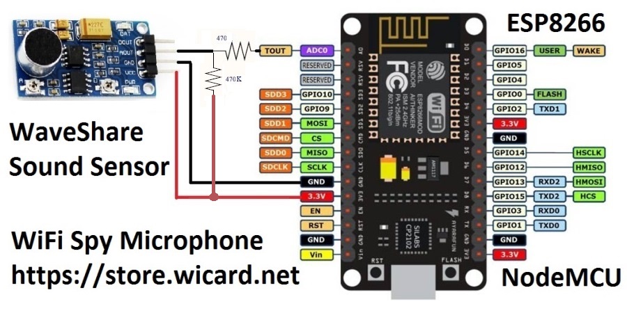
The circuit with "NodeMCU" and "Waveshare Sound Sensor":
First open one of the files with Arduino program, then set the settings as the following image (Board, CPU Frequency and Flash Frequency):
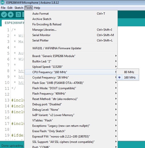
- The �Board� must be set on one of the ESP8266 Modules before doing anything.
- The CPU Frequency must be set on 160 MHz.
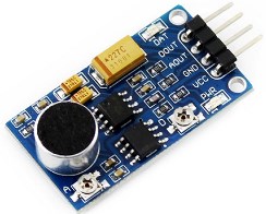
Microphone Module
You can either use WaveShare sound senor, MAX9814 or any of the other compatible microphone modules. The analog output of the microphone module must be between the allowed input voltage of the esp8266 module.
The allowed voltage for esp8266MOD modules is between 0 to 1 volt and for the esp8266 NodeMCU modules is between 0 to 3.3v.
You can calibrate the microphone module output voltage with the load and pull up/down resistors.
Also you can use the oscilloscope in the “Network” menu of the project’s web UI (WebApp) for the calibration.
Consider it that In the NodeMCU modules, there are internally load and pull up/down resistor to convert the 0-3.3v input to 0-1v for the esp8266 A0 pin.
WaveShare Sound Sensor
WaveShare sound sensor is an audio amplifier and sensor with LM386. This module is compatible with this project.
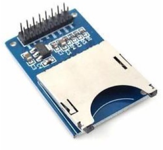
Auto Voice Recorder
You can either use a prepared SD/MMC memory card module (with resistors and the 3.3V regulator) or use a slot and add the resistors to your circuit.
In case you are using NodeMCU, it�s suggested to use a memory module with a 3.3V regulator and supply it with 5V (�Vin�), because it reduces the ESP module�s power supply noises and the ESP module�s internal regulator heat.
For recording the voices automatically, insert a memory card, turn on the module and select the sensitivity (10db, 20db and 30db for the louder noises).
Then the device starts to hearing the noises and as soon as hearing the load enough noise, it starts to recording it in a .wav file with the selected quality and record time.
When the recording is finished, the file will be available in the file manager.
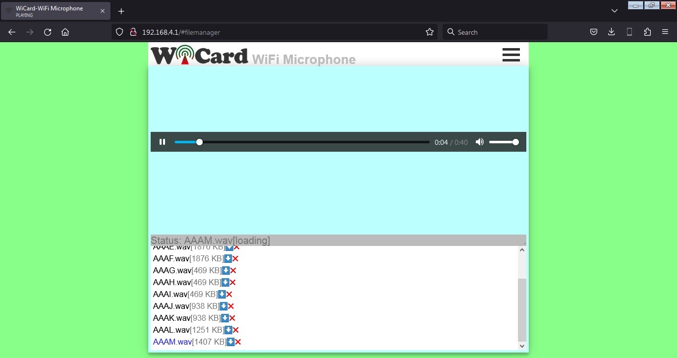
- You can record the audio and listen to the stream online at the same time, but in this situation, the quality may reduce.
- Opening the file manager stops the recording.
- The LED will blink during recording
ESP8266 WiFi Spy Microphone Schematics
It�s suggested to use a standard 3.3V microphone module (like �WaveShare Sound Sensor�). The ADC pin (A0) of esp8266 is the audio signal input. Before using the WiFi microphone, build one of the following circuits.
Here�s a suggested circuit with a simple capacitive microphone, LM386 and ESP8266MOD (ESP12):
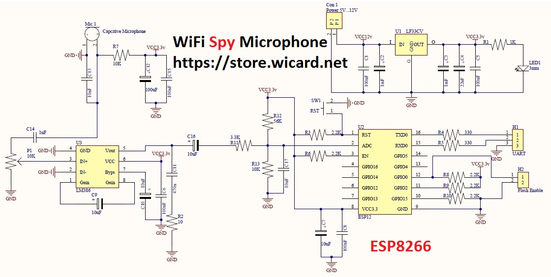
In the above schematic (LM386 and ESP8266MOD), LED1 shows the power is on, SW1 is the ESP8266 module reset button, H1 is the module�s UART connector (for flashing/programming) and H2 pin header needs a jumper to put the ESP12 module in the flash programming mode.
The microphone block has a potentiometer (P1) to calibrating the input audio signal. In the low level, the audio noise will decrease but the output audio is weaker and in the high level you can hear the small voices but more noisy.
- Better to use a 5-12V power source with 2A output drain capability.
- The module must only receive 3.3v (from the LF33 regulator). Higher voltage will hurt the module.
The Chain Network
The �Chain Network� is a local network which the devices one by one are connected to the each other (Series). In the chain network, the first device is the master of network. The starter (either the master or the last joined module) is directly connected to the WebApp. It sends the command to the next device, and the next device sends it to the next one till the last device. The last device response will be sent to the first device and finally the WebApp via the middle devices.
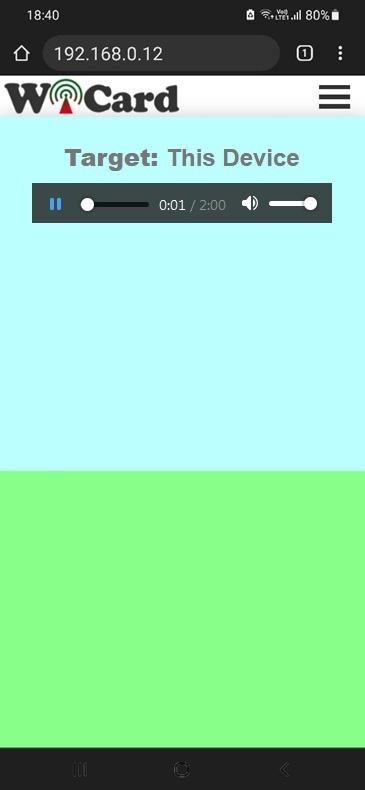
The ESP8266 WiFi Microphone Web Application
Plug the power and turn on the circuit and the module in �normal mode�.
Then in case you are using ESP12, the blue LED on the board would be turned on. Then you�ll be able to see the module�s hot spot ssid via the WiFi networks in your PC or smart phone.
The default SSID is WiCardMic and the default password is 12345678. Connect and go to 192.168.4.1 with a PC or smart phone web browser (Chrome or Firefox).
Here�s the web UI:
Right after loading the page, the module starts recording and buffering automatically. By clicking on the play button, the recorded sound will play.
This page records audio data to in the browser�s cache automatically. Also you can play the audio and listen to the audio lively at the same time.
- It�s suggested before click on the play button, wait for a few seconds for buffering.
The preset time can be 5, 10, 30 and 60 minutes. After this time spent, you can refresh the page and record again.
To downloading the audio file directly, go to 192.168.4.1/0 (or the router�s given IP).
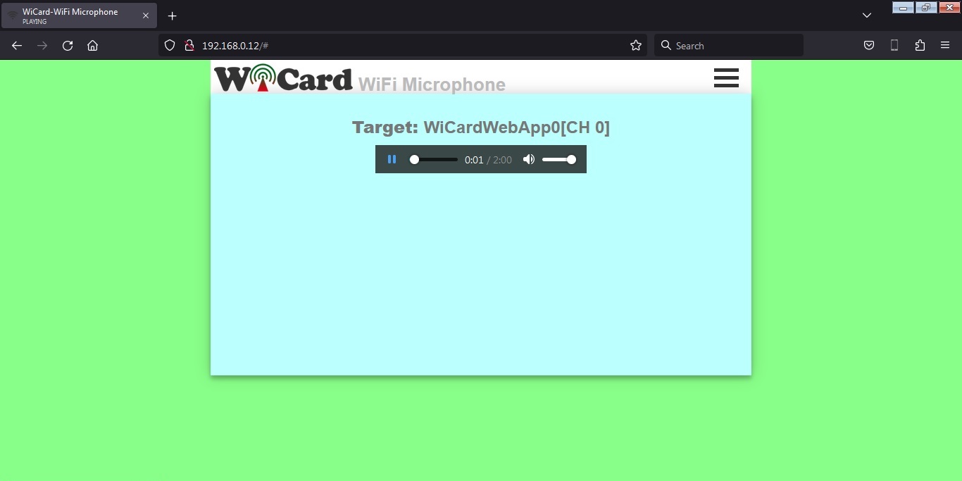
Above of the audio player, you can see the target device.
- If you close the web page, recording will be aborted.
- Do not open two pages at the same time. The module can handle only one page at a time.
- The WiFi signal strength takes effect on the module capability and the audio streams.
- This web application is also compatible with cell phone and mobile device browsers.
The menus
The Web Application is divided to 4 menus. The menus can be selected by click on the menu button.
�Online Stream� refers to the �Live Audio Player� page, �Network� refers to the Network WiFi Microphone Monitor (oscilloscope), "File Manager" refers to the memory card access and �Settings� refers to the settings and configuration page.
The Network Oscilloscope and Monitors
In the �Network� page, there are 4 scope/monitor channels. That means you can add up to 4 devices, either WiCard Microphone or WiCard Camera to the chain network and see the audio signals or online video streams at the same time.
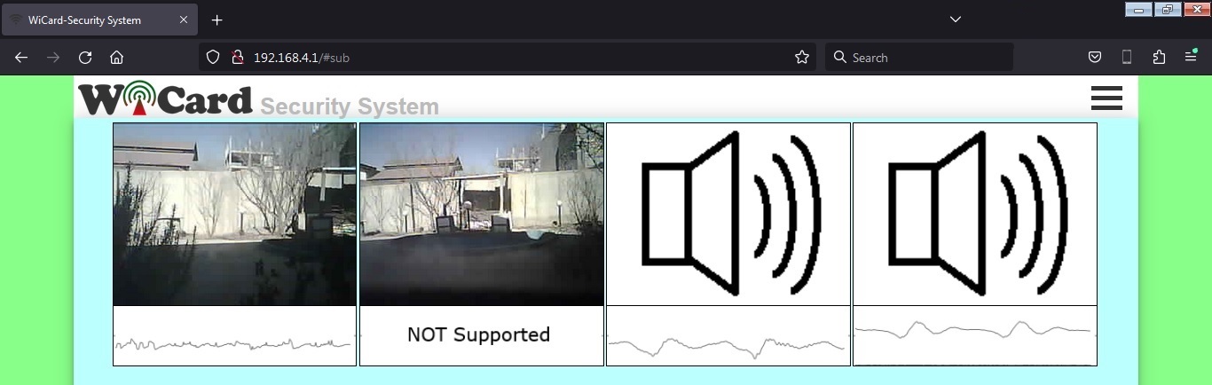
In the above picture, only two devices (CH0 and CH1) are connected to the network.
By click on each channel, the target device in the audio player page will change to the selected device.
The Settings menu
The web application�s settings menu has been divided to 5 parts:
- Modem Configuration
In this section you can see the available access points, the connection status, the device MAC address and the DHCP IP.
Also in this section you can set the SSID and password of the modem�s access point.
If the modem is not available, clear the SSID text box and save it. - Device Hotspot Configuration
In this section you can set your module�s hotspot SSID and password.
The secure link is a string which will be added at the end of your module�s IP address. For example if you set it �123�, the IP address of the WebApp of your module will be 192.168.4.1/123 instead 192.168.4.1
The even means the default IP is 192.168.4.1, the Odd means the default IP is 192.168.5.1
Hidden HotSpot will set the HotSpot hidden.
Temporary HotSpot will disable the HotSpot right after the module is connected to the modem or joined to the network (For the last device in the network).
The SSID must be without space in case you�re going to join the device to the network. - Microphone Configuration
In this section:
You can set the device�s network channel. The channel must be a number between 0-7 and the devices can�t have the same channel.
The �Audio Stream Sample Rate� can be 12, 24 or 44 KHz.
The �Audio Stream Packet Length� can be 5, 10, 30 or 60 minutes.
The �Audio Stream Resolution� can be 8 or 10 bit.
For 240Kbps, set the sample rate to 24 KHz and resolution to 10 bit. - Local Network Configuration
In this section you can set the �Master� device and also set the userGlobal() function execution delay.
The linked WiCard IP is the IP of linked device to the module�s access point.
If you don�t turn on the �Join Required� switch, the module will be set as Master - Local Network Map
In this section, the attached devices in the chain network will be shown.
For the master, it starts with master�s SSID, then the second ESP device, until the last one, but for the last device, the sort is vice versa.
With typing the target device SSID in the target text-box, the oscilloscope will show the target device signal.
Both of ESP32 and ESP8266 can transfer the audio data of the other modules in the network.
Programming Manual
For the programming, use the pre-defined functions in the files which start with �user�.
Add your start-up script to the �userInit()� function in user_init.ino file. No need to do wifi or server configuration. This configuration already have done in the firmware system files (e.g. systemInit() and setup()).
The �userLoop()� function (user_loop.ino) calls repeatedly (like arduino �loop()� function), If your program needs to execute a statement repeatedly (e.g. reading a sensor�s data), insert your script in this function.
The �webapp.h� file is the root page�s script. You can customize sWebApp variable in that file if you�re going to make changes in the Web UI.
Also you can customize the �userGetSettings()� function (user_settings.ino), for adding more settings to the firmware. The WebApp execute this function when you click on the Settings menu.
After you click on the SAVE button of the user-defined settings, the �userSetSettings()� functions will be called.
- The settings will not be shared in the network and each device has its own settings.
The �userMain()� in the �user_main.ino� file, calls once when you click on the �Player� menu (or initially after loading the root page).
The �userSubInit()� in the �user_sub.ino� file, calls once when you click on the �Network� menu and sends the available devices in the network back..
The �userSub()� in the �user_sub.ino� file, calls intervally and the starter collects the scope data in the chain network.
- The �networkStarterCheck()� bool functions says whether the module is the network starter or not.
The �userGlobal()� function in the �user_global.ino� is not working in this revision.
In the AC.h file, if you remove �#define LOG_ENABLE�, the logs will not be shown and the log memory would be released.
In the user_global.h file, you can change the bit-rate timing and delays with the following �define� variable:
#define AUDIO_6KHZ_DELAY 140
#define AUDIO_12KHZ_TIMING 80
#define AUDIO_18KHZ_TIMING 54
#define AUDIO_24KHZ_TIMING 39
Also you can change the buffer sizes with the following variables.
#define AUDIO_BUFFER_SIZE 3900
#define AUDIO_NET_BUFFER_SIZE 100
- If you have not enough programming and electronics knowledge, do not make changes.
- The WiFi signal strength takes effect on the module capability and the streams.
3.0
- Stream quality increased up to 441Kbps
- Bugs fixed
- Recorded output file fixed
2.1
- Compatibility of Camera devices for the Network feature
- Bugs fixed
- Network quality increased to 240kbps
- Online Audio stream added for the SpyCam devices in the network
- File manager upgraded
2.0
- Memory card reader added to the hardware
- Voice recorder added to the software
- File manager added to the WebApp
1.6
- The audio noises reduced
- The network audio quality increased to 64Kbps
- Page loading speed increased
- Buffer size increased
- Connection secured with upgrading the secure link feature
- Auto network channel and target selector added
1.5
- The Web Ui upgraded
- Bit-rate and the quality of audio stream increased (240Kbps)
- Network stream feature added
- Network monitor feature added
1.4
- Bit-rate increased up to 110Kbps
- SecureLink bug fixed
1.3
- Schematic improvement
- The Web UI has been changed
- increasing the quality of the recorded sound
- Increasing the bitrate up to 100kbps
- reducing the noises
- Bugs fixed
1.2
- Schematic improvement
- Secure link debug
- ADC input improvement
- Output file improvement
- Selectable stream quality
- Adjustable stream time
- Adjustable software amplitude
1.1
- 10:28 frame (increased)
- Audio stream recorder and player
- 8KHz sample rate (increased)
- 10 bits resolution (increased)
- Calibration page
- The stability and quality of audio stream increased
- Suggested test circuit updated
- Bugs fixed
1.0
- 3300 miliseconds frames
- LOUD button
- 7.5KHz sample rate
- 8 bits resolution
- Internal pages secure link
- Show MAC and IP in config page
- Set module hotspot and modem�s ssid and password
- Automatically connection to the modem
- Config page
- Hidden hotspot button
- Disable hotspot button
Similar Projects: