Other projects from this group
WiCard Security System Package (WiFi Microphones and Cameras)
This is a package of 4 projects, ESP8266 WiFi Microphone, ESP32 WiFi Microphone, ESP32-Cam IP Camera and ESP32-Cam SpyCam (Camera and Microphone).
WiCard Security System Package (ESP32/ESP8266 Microphone and Camera) - Rev 2.1
Price:
Other projects from this group
This package is WiCard Security System which includes the following project source codes and manual files:
- ESP8266 WiFi Microphone: This project is a firmware for ESP8266 WiFi modules and sound sensor/module which can stream and record voices.
- ESP32 WiFi Microphone: This project is a firmware for ESP32 WiFi modules and sound sensor/module which can stream and record voices.
- ESP32-Cam IP Camera: This project is a firmware for ESP32-Cam modules which can stream and record videos.
- ESP32-Cam SpyCam: This project is a firmware for ESP32-Cam modules and sound sensor/module/board which can stream and record audio and videos.
You can either use the projects separately or join them in a local network and access to the devices via “Network” page of the web application.
Each project has a separate manual file to describe how to use the projects.
Uploading the projects firmware
The projects can be uploaded into the modules with Arduino IDE software. Before uploading the projects firmware, install “ESP32 board rev 2.0.14” and “ESP8266 board rev 3.1.2”.
Then select the compatible board according to the project, plug your module and click on the upload button.
Then turn on the ESP32 module in the “download mode” (GPIO0àGND) and upload the program with using an USB2Serial module.
- In the some ESP board, you need to connect GPIO0 to the GND before power on to upload the firmware.
- It’s suggested to remove the whole data in the ESP flash memory before the first upload.
The Chain Network of WiCard Security System
The “Chain Network” is a local network which the devices one by one are connected to the each other (Series). In the chain network, the first device is the master of network. The starter (either the master or the last joined module) is directly connected to the WebApp. It sends the command to the next device, and the next device sends it to the next one till the last device. The last device response will be sent to the first device and finally the WebApp via the middle devices.
You optionally can join up to 4 devices, either with “ESP32 SpyCam” firmware (Audio and Video recorder and streamer), “ESP32 IP Camera” firmware (which has not the audio feature), “ESP32 WiFi Microphone” or “ESP8266 WiFi Microphone” rev 2.1 in a chain network and see the online stream of the Cameras and the audio signals.
Here’s the block diagram of how the chain network in this project works:
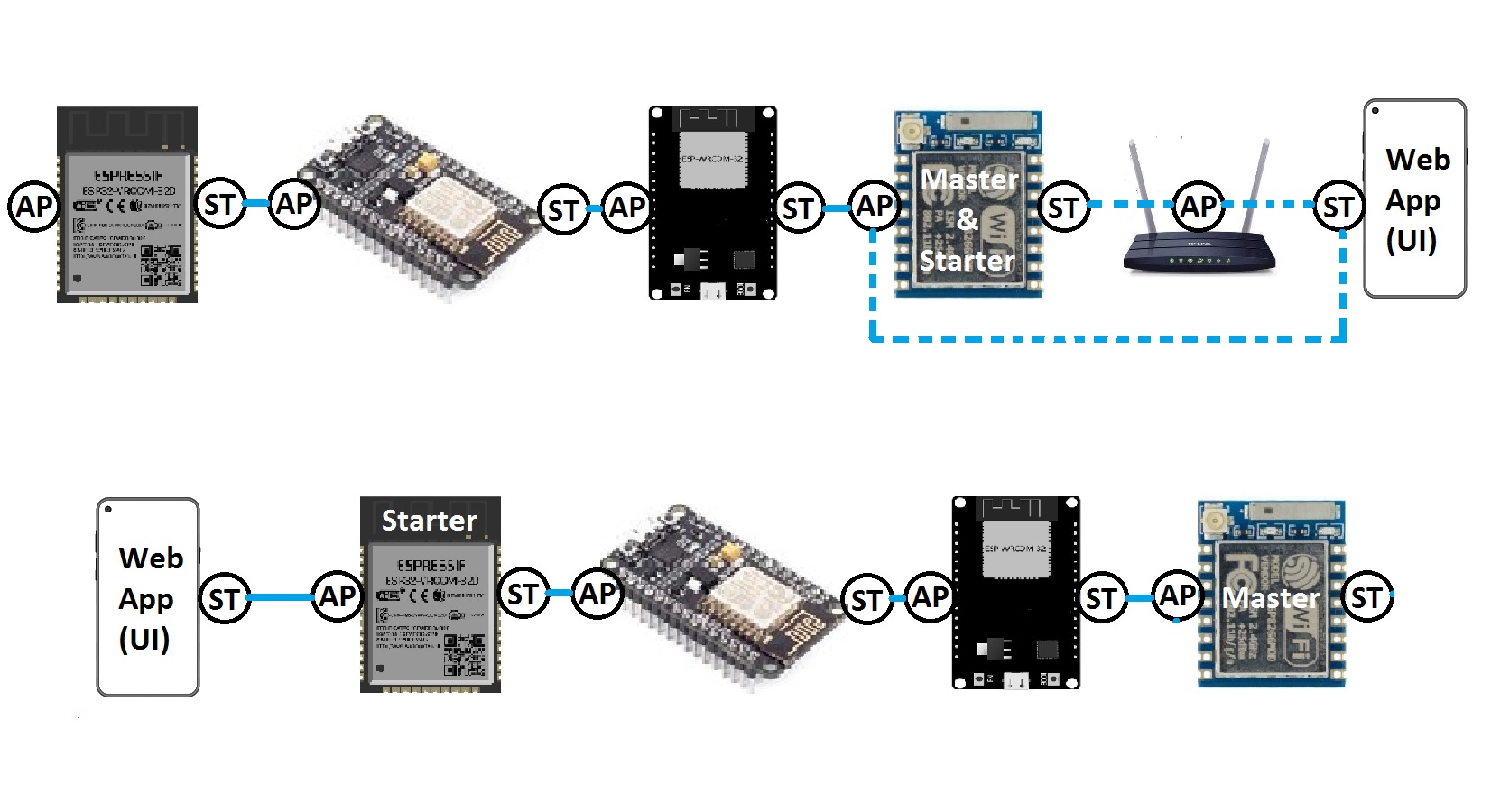
Figure 1-The chain network
In the first diagram, the Master is the starter and either can be connected to the WebApp via a router with its WiFi Station (ST) or can connect directly to the WebApp with its WiFi Access Point (AP-Hot Spot). The second module is connected to the Master’s AP, The third one is connected to the Second one’s AP and the last one is connected to the third AP via its own ST.
In the second diagram, The WebApp in a smartphone has been connected to the last device in the network and the last one is the network starter.
The Security System Web Application
Plug the power and turn on the circuit and the module in “normal mode”.
Then the LED will blink once (in case of everything is ok). Then you’ll be able to see the module’s hot spot ssid via the WiFi networks in your PC or smart phone.
The default SSID, depending on the project, should be WiCardMic, WiCardCam or WiCardCamMic and the default password is 12345678.
Connect to the SSID and go to 192.168.4.1 with a PC or smart phone’s web browser (Chrome or Firefox).
The Web Application is divided to 4 menus. The menus can be selected by click on the menu button (%26nbsp;%26nbsp;%26nbsp;%26nbsp;%26nbsp;%26nbsp; %26nbsp;%26nbsp;):
- Online Stream: Shows the main page and online video stream.
- Network: Shows the network video streams and audio signals.
- File manager: access to the files which are saved in the memory card.
- Settings: WiFi and system configuration.
 Online Stream
This is the default page and you can see the online video stream and/or audio in this page.
Network
This menu shows a small-sized video stream or audio signal. Optionally you can add up to 4 devices (CamMic, Camera and/or Microphone rev 2.1 of the firmware with “Chain Network” feature) in a network and see the online video streams and audio signals (in the oscilloscope under each channel) at the same time.

Figure 2-Network Online Stream
The channels can be the same modules or mixed (Camera, Microphone, CamMic).
By double click (or double tap) on each images or click on the oscilloscope, you can see the original quality of the camera in the network.
- Do not open two or more pages at the same time. The module can handle only one page at a time.
- The WiFi signal strength takes effect on the module capability and the video streams.
- The power supply must drain enough current and stable voltage for better performance.
- ESP32 module is weak and the arduino ESP32 compilers still needs to be updated and improved, so when the module’s access point (hotspot) is turned off (by connecting the module to a modem and turning the temporary hotspot button on in the settings page), the device has a better performance.
- This web application is also compatible with cell phone and mobile device browsers.
- Do not refresh the page during the stream. To reloading the page, first close the stream page and then go to the web app address again after a few seconds.
- The data band-width is limited, so in the audio and video stream mode, if you increase the quality of the video stream, the quality of the audio stream may decrease.
- In the “Chain network” feature, the last target device has less band-with and delay.
- The power consumption increases in the network mode, because both of station and access point are enabled and connected. So each module needs a standard power source. Also the recording increases the power consumption. It’s suggested to use external memory module with an onboard 3.3v regulator and external lights.
- You can access directly to the network page by http://ip#sub link (ip is the module’s IP).
File Manager
There’s a file manager menu in the application which shows the files in the root directory of the memory card. Each file can be downloaded by click on the download button.
The supported files (.jpg .jp4 .jp5 .wav .mp3) can be selected and played in the web application.
The .jp4 and .jp5 files can be exported as .avi file by click on the export button. You can open the .avi file with “BS Player”, “VLC”, “KM Player” or any other standard multimedia software. Also the files can be edited by standard video makers like “Video Match”.
You can remove any file by click on the remove button.
By click on the play button (middle of the JP5 file image), the video will be downloaded and played along with the audio and you can pause the video by tap or click on the image.
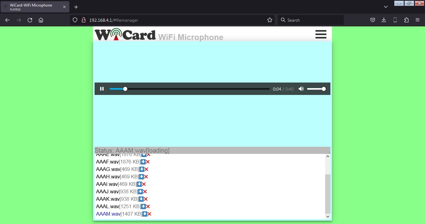
Figure 3-The File Manager and Audio Player
- Downloading or exporting the videos may take a while, it depends on the video data length and the WiFi signal strength.
- Optionally you can access to the file manager of the devices in the network, by selecting the target device in the settings menu.
- You can access directly to the network page by http://ip#filemanager link (ip is the module’s IP).
Settings
The web application’s settings menu has been divided to 5 parts:
- Modem Configuration
In this section you can see the available access points, the connection status, the device MAC address and the DHCP IP.
Also in this section you can set the SSID and password of the modem’s access point.
* If the modem is not available, clear the SSID text box and save it. - Device Hotspot Configuration
In this section you can set your module’s hotspot SSID and password.
The secure link is a string which will be added at the end of your module’s IP address. For example if you set it “123”, the IP address of the WebApp of your module will be 192.168.4.1/123 instead 192.168.4.1
The even means the default IP is 192.168.4.1, the Odd means the default IP is 192.168.5.1
Hidden HotSpot will set the HotSpot hidden.
Temporary HotSpot will disable the HotSpot right after the module is connected to the modem or joined to the network (For the last device in the network). - Device Configuration
You can configure your device, or enable/disable its features in this section. - Local Network Configuration
In this section you can set the “Master” device and also set the userGlobal() function execution delay (which in not used in this revision).
The linked WiCard IP is the IP of linked device to the module’s access point.
If you don’t turn on the “Join Required” switch, the module will be set as Master. - Local Network Map
In this section, the attached devices in the chain network will be shown.
For the master, it starts with master’s SSID, then the second ESP device, until the last one, but for the last device, the sort is vice versa.
With selecting the target device SSID in the target text-box, you can access to the target device’s memory.
With the target feature, you can access to both of SpyCams and IPCams (rev 1.4) memories and play the .JP4 and .JP5 videos.
- You can directly access to the settings menu with http://ip#settings link (e.g. 192.168.4.1#settings).
An Example of WiCard Security System Network
In the following image, the first channel is SpyCam firmware, the second channel is IP Camera device which doesn’t support audio, the third channel is ESP8266 WiFi Microphone and the fourth channel is ESP32 WiFi Microphone.
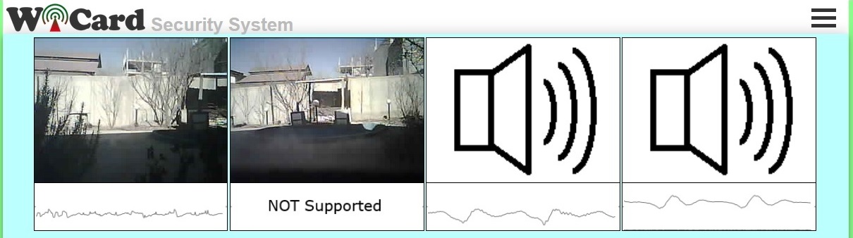
Figure 4-Example Network
The first channel can be connected to WiFi router, so you can insert your WiFi modem SSID and password in the “Modem Configuration” of the settings.
In the “Device Hotspot Configuration”, the default IP is set on “Even” (192.168.4.1), the hotspot optionally can be hidden or not and the “Temporary Hotspot” must be disabled.
The “Join Required” in the “Local Network Configuration” section must be off for the first device.
The second channel must be connected to the first device’s SSID in the “Modem Configuration” of the settings.
In the “Device Hotspot Configuration”, the default IP must be set on “Odd” (192.168.5.1), the hotspot optionally can be hidden or not and the “Temporary Hotspot” must be disabled.
The “Join Required” in the “Local Network Configuration” section must be enabled.
The third channel must be connected to the second device’s SSID in the “Modem Configuration” of the settings.
In the “Device Hotspot Configuration”, the default IP must be set on “Even” (192.168.4.1), the hotspot optionally can be hidden or not and the “Temporary Hotspot” must be disabled.
The “Join Required” in the “Local Network Configuration” section must be enabled.
The fourth channel must be connected to the third device’s SSID in the “Modem Configuration” of the settings.
In the “Device Hotspot Configuration”, the default IP must be set on “Odd” (192.168.5.1), the hotspot optionally can be hidden or not and the “Temporary Hotspot” can be disabled or enabled.
The “Join Required” in the “Local Network Configuration” section must be enabled.
As the result, you can see all of the devices and channel in the network map section.
* It’s suggested turn on the devices with a one minute delay in the order
2.1
- ESP8266 WiFi Microphone Firmware rev 2.1 added
- ESP32 WiFi Microphone Firmware rev 2.1 added
- ESP32-Cam IP Camera Firmware rev 2.1 added
- ESP32-Cam SpyCam (WiFi Camera and Microphone) Firmware rev 2.1 added