Other projects from this group
MAX30100 Pulse Oximetere With Arduino UNO and Keypad LCD Shield
This project is the source code and schematic of a “MAX30100 Pulse Oximeter” With “Arduino UNO” board, “DF ROBOT” keypad/LCD shield.
Oximeter with MAX30100, Arduino UNO and LCD Shield - Rev 1.0
Price:
Other projects from this group
MAX30100 Pulse Oximeter is a module which can help to calculate oxygen saturation percent in the human’s blood with two RED and Infrared LEDs.
The output data form MAX30100 is so many samples in a second which contains LEDs reflection ADC value.
This project contains a folder UNOPulseOximeter (the arduino source code) which contains 5 files:
1-%26nbsp;%26nbsp; %26nbsp;UNOPulseOximeter.ino – the main program
2-%26nbsp;%26nbsp; %26nbsp;I2C.ino (I2C comminucation handler)
3-%26nbsp;%26nbsp; %26nbsp;I2C.h (I2C comminucaton headerfile)
4-%26nbsp;%26nbsp; %26nbsp;MAX30100.ino (The oximeter module handler)
5-%26nbsp;%26nbsp; %26nbsp;MAX30100.h (The oximeter module headerfile)
First open one of the files with Arduino program, then set the board on “Arduino UNO” (Toolsboard).
Compile and upload the program and wait until the LCD turns off and then turns back on.
The screen will show the SPO2 value after a few seconds.
•%26nbsp;%26nbsp; %26nbsp;Try to wrap something around your finger and the MAX30100 module, because this module is very sensitive on the peripheral lights.
•%26nbsp;%26nbsp; %26nbsp;This is not a medical project even if the value be accurate. Please do not use for the patients.
Errors in Logs
Open arduino “serial monitor” when the system is connected to the USB. If you receive I2C error, that means the wiring/connection is not correct.
If you received “e2” error, that means finger is not on the MAX30100 sensor.
It is normal to receive “e3” rarely, but if the error is too much, that mean the finger is not completely on the sensor or the module is receiving peripheral lights.
The Schematic
Here’s the tested schematic which uses only 4 wires for the module.
%26nbsp;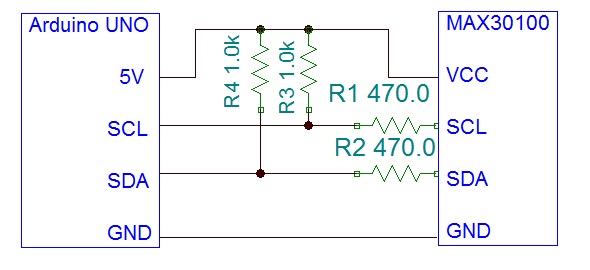
The project has been tested with 1K pull up resistors and 470 Ohm load resistors, as the schematic says.
1.0
-Calculating SPO2
-Printing the value on the LCD