Other projects from this group
ESP8266 WiFi Oscilloscope+Network Volt meter Arduino Source Code
With this source code, an ESP8266 (or NodeMCU) module and a 3.3v power source, build a WiFi oscilloscope (70Ksps*10bit Analog, 3Msps Digital)+network volt meter
ESP8266/NodeMCU WiFi Oscilloscope+Network Volt Meter Arduino Source Code - Rev 1.2
Price:
Other projects from this group
This project is an ESP8266 WiFi Oscilloscope firmware with Network Volt Meter.
This project is based on the “ESP8266 WebApp Builder” project which is a base source code with the chain network feature.
There are the following files in this project:
- ESP8266WebApp.ino (Main handler file)
- AC.h (Configuration header file)
- AC.ino (Configuration handler file)
- functions.ino (System functions)
- rootPage (UI handler file)
- user_global.h – Project global variables and definitions file.
- user_init.ino – Project initial script file.
- user_loop.ino – This file has a “userLoop()” function which calls repeatedly (like arduino “loop()” function).
- user_settings.ino – Project settings file.
- user_main.ino – Oscilloscope handler script.
- user_sub.ino – Network volt meter handler script.
- user_global.ino – This file has a “userGlobal()” function which calls at the same time in all of the devices in the network. This function will be called when the app sends a command to the network (after userMain and userSub).
- Webapp.h – This file contains the WiFi Oscilloscope WebApp’s script.
- Manual PDF file
ESP8266 WiFi Oscilloscope Input Pins
The ADC pin of ESP8266 module is the analog input and the default digital input pin is GPIO 05.
The input range of analog signal for the ADC pin is between 0-1V for the ESP8266 modules and between 0-3.3V for the NodeMCU modules.
With the suggested circuit in the manual file, the input signal voltage can be vary between 0-12V
The input of digital signal should be 0V (LOW) or 3.3V (HIGH). If your digital “High” voltage may be up to 5V, you can use the suggested circuit in the manual file as the voltage divider:
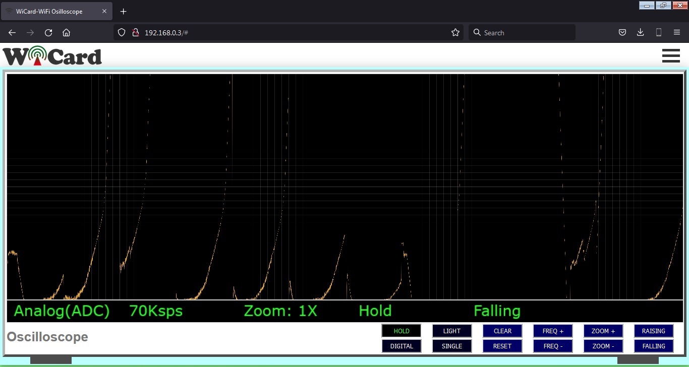
The WiFi Oscilloscope’s Web Application
The WiFi oscilloscope project has a nice and responsive web application which is placed in the root page address (192.168.4.1 by default and can be set to 192.168.5.1 or you can use the router’s DHCP IP).
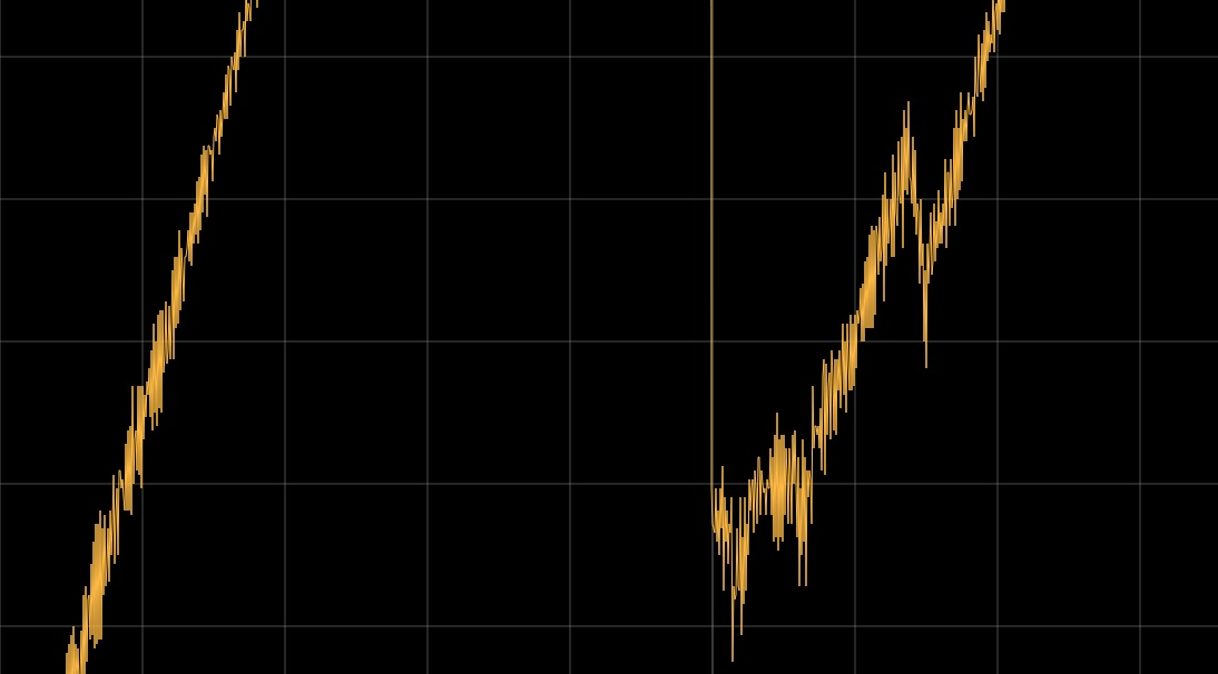
The screen resolution is 12288x4096 pixels. By click on the screen you can download the Graph file in .png format and the zoomed result would be like this:
There are 4 toggle buttons under the scope screen:
- HOLD: Holds the capturing.
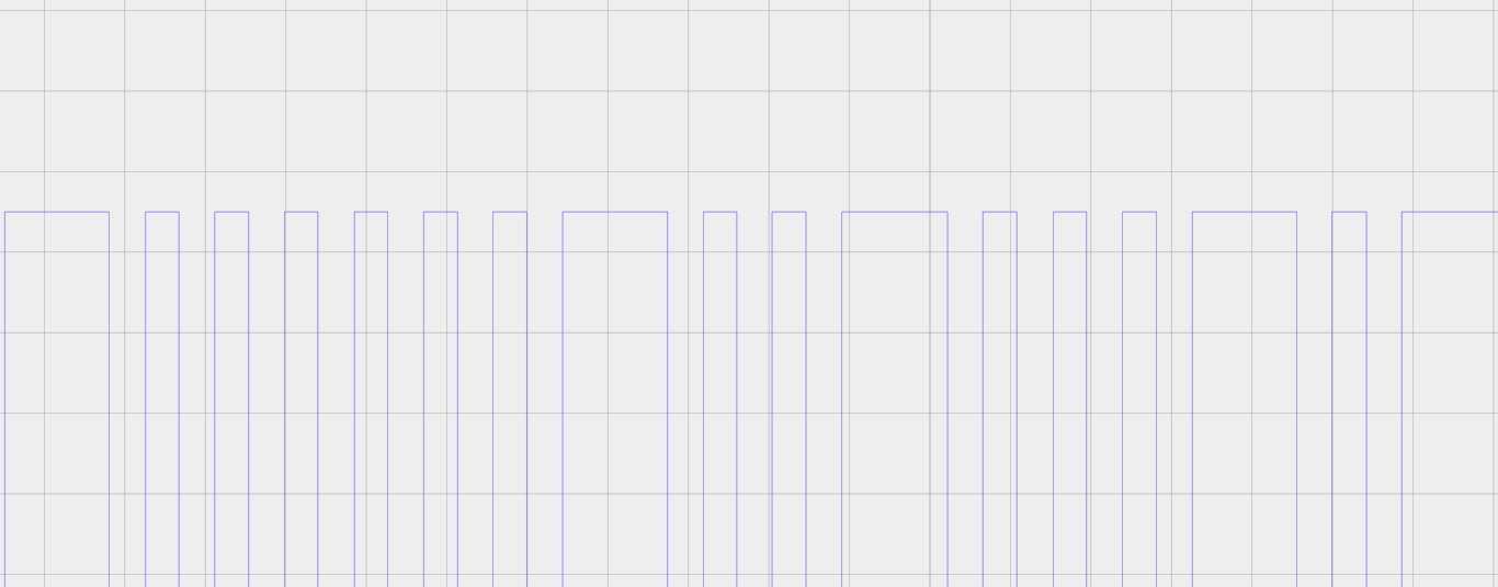
- LIGHT: Toggles between the light and dark theme.
- DIGITAL: Toggles between “Digital” channel and the “Analog” channel.
- SINGLE: Enables and disables the “Single Shot” mode. That means the screen will be updated only once.
And 8 push buttons under the scope screen:
- CLEAR: Clears the screen and re-captures the signal.
- RESET: Clears the screen and capturing mode (Falling/Raising).
- FREQ+: Increases the sampling frequency.
- FREQ-: Decreases the sampling frequency.
- ZOOM+: Zooms In the analog signal to 4X from Zero
- ZOOM-: Zooms out the analog signal to the original.
- RAISING: Sets the capturing mode to the “Raising mode”. That means the screen will be cleared and the scope stops sampling. Then if the analog signal voltage increases or the digital signal state changes from LOW to HIGH, the sampling will start.
- FALLING: Sets the capturing mode to the “Falling mode”. That means the screen will be cleared and the scope stops sampling. Then if the analog signal voltage decreases or the digital signal state changes from HIGH to LOW, the sampling will start.
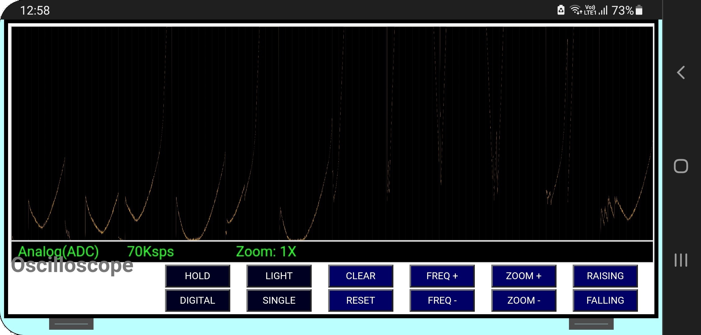
The responsive WebApp
This web application is also compatible with cell phone and mobile device browsers:
The menus
The Web Application is divided to 3 menus. The menus can be selected by click on the menu button.
“Oscilloscope” refers to the WiFi Oscilloscope page, “Volt-Meter” refers to the Network Volt Meter page and “Settings” refers to the settings page.
The Network Volt Meter
In the “Volt-Meter” page, there are 16 channel rows of the volt meters result. That means you can add up to 16 devices to the chain network and see the values.
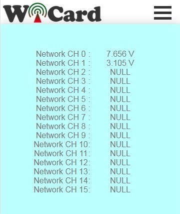
In the above picture, only two devices (CH0 and CH1) are connected to the network.
The “Volt Meter’s Network Channel” can be set in the settings menu.
- The maximum value is 12VDC.
The Settings menu
The web application’s settings menu has been divided to 5 parts:
- Modem Configuration
In this section you can see the available access points, the connection status, the device MAC address and the DHCP IP.
Also in this section you can set the SSID and password of the modem’s access point. - Device Hotspot Configuration
In this section you can set your module’s hotspot SSID and password.
The secure link is a string which will be added at the end of your module’s IP address. For example if you set it “123”, the IP address of the WebApp of your module will be 192.168.4.1/123 instead 192.168.4.1
The even means the default IP is 192.168.4.1, the Odd means the default IP is 192.168.5.1
Hidden HotSpot will set the HotSpot hidden.
Temporary HotSpot will disable the HotSpot right after the module is connected to the modem or joined to the network (For the last device in the network). - System Configuration
In this section, you can set the device’s network volt meter channel.
The channel number must be between 0-15 and the devices can’t have the same channel. - Local Network Configuration
- Local Network Map
- You can directly access to the settings menu with http://ip#settings link (e.g. 192.168.4.1#settings).
Programming Manual
For the programming, use the pre-defined functions in the files which start with “user”.
Add your start-up script to the “userInit()” function in user_init.ino file. No need to do wifi or server configuration. This configuration already have done in the firmware system files (e.g. systemInit() and setup()).
The “userLoop()” function (user_loop.ino) calls repeatedly (like arduino “loop()” function), If your program needs to execute a statement repeatedly (e.g. reading a sensor’s data), insert your script in this function.
The “webapp.h” file is the root page’s script. You can customize sWebApp variable in that file if you’re going to make changes in the Web UI.
Also you can customize the “userGetSettings()” function (user_settings.ino), for adding more settings to the firmware. The WebApp execute this function when you click on the Settings menu.
After you click on the SAVE button of the user-defined settings, the “userSetSettings()” functions will be called.
- The settings will not be shared in the network and each device has its own settings.
The “userMainInit()” in the “user_main.ino” file, calls once and only just in the network starter when you click on the “Oscilloscope”menu (or initially after loading the root page). You can initiate the uiAppData in this function.
The “userMain()” in the “user_main.ino” file, calls intervally or by clicking on the “Oscilloscope” menu elements. The WebApp will send the uiAppData to this function and then it can be transferred in the chain network.
The “userSubInit()” in the “user_sub.ino” file, calls once and only just in the network starter when you click on the “Volt-Meter” menu.
The “userSub()” in the “user_sub.ino” file, calls intervally or by clicking on the menu elements. The WebApp will send the uiAppData to this function and then it can be transferred in the chain network.
- Only if you call “globalCmdEnable();” function at the end of “userMainInit()”, “userMain()”, “userSubInit()” and “userSub()”, the uiAppData will transferred in the chain network.
- The “networkStarterCheck()” bool functions says whether the module is the network starter or not.
The “userGlobal()” function in the “user_global.ino” file calls at the same time in all of the devices in the chain network after the “CMD delay” time.
- If you are going to use this function, set the menu’s interval time to 0.
- This function always will be called after setting the “globalCmdEnable()”.
- It’s recommended to use a bool variable when you are going to use this function after a change in an element occurs.
In the AC.h file, if you remove “#define LOG_ENABLE”, the logs will not be shown and the log memory would be released.
In the user_global.h file, you can set the default digital channel by the following “define” variable:
#define%26nbsp;%26nbsp; DIGITAL_CH_PIN%26nbsp;%26nbsp;%26nbsp;%26nbsp;%26nbsp;%26nbsp;%26nbsp;%26nbsp;%26nbsp;%26nbsp;%26nbsp; 5
And you can set the analog raising and falling detection threshold value by the following variables:
#define%26nbsp;%26nbsp; ADC_R_THR%26nbsp;%26nbsp;%26nbsp;%26nbsp;%26nbsp;%26nbsp;%26nbsp;%26nbsp;%26nbsp;%26nbsp;%26nbsp;%26nbsp;%26nbsp;%26nbsp;%26nbsp;%26nbsp; 20
#define%26nbsp;%26nbsp; ADC_F_THR%26nbsp;%26nbsp;%26nbsp;%26nbsp;%26nbsp;%26nbsp;%26nbsp;%26nbsp;%26nbsp;%26nbsp;%26nbsp;%26nbsp;%26nbsp;%26nbsp;%26nbsp;%26nbsp; 20
- If you have not enough programming and electronics knowledge, do not make changes in the system files.
1.2
-Sample rate increased to 70Ksps
-Digital channel added (3Msps)
-Screen resolution increased to 4096*12288
-12 Buttons and features added
-Network volt meter added
1.1
-The Web Ui upgraded
1.0
-256x1000 pixel screen
-Sample speed button
-Internal pages secure link
-Shop MAC and IP in config page
-Set module hotspot and modem’s ssid and password
-Automatically connection to the modem
-Config page
-Hidden hotspot button
-Disable hotspot button